Vision Example Questions

Hi,

I’m trying to make a few changes to the Vision example for mnist.
To make it a little more … CNN-like
My plan is to try and make a SCNN that can work with single spike instances, then eventually work with a spike-timing learning rule. My alternative approach seems to be hand-coding all the individual pixels to do this, but i imagine there must be a more efficient way

i change the Gabor to a predefined 5x5 kernel and i am only testing it on one feature just now.
i also change the receptive field locations from randomly sparse to sequential with a stride of one.

So i should have 576 output from this, which i do :slight_smile:
but when it comes to taking the values out of the Mask.populate function is when i am getting confused

i get a 576,784 tuple which is cool 576 28x28s flattened

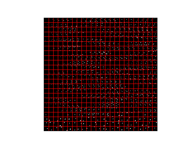
but when i try to tile to see what the representation of this is the kernels are now randomly spread across different masks :frowning:

Figure_1

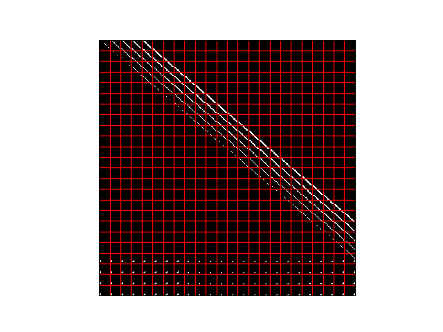
the bottom few rows almost look good but the rest is just confusing…

?? Is this just the tiling program and all the reshaping making it look odd, or is this what the neurons i have ensembled are doing ??

Hello Paul,

Would you be able to post your code for creating the 576 x 784 weight matrix, as well as your code for visualizing it? The problem could be as simple as some axes getting swapped somewhere along the way.

Hi Eric,

Thanks for your reply, I have added the code below…

I mean this could all be a contrived example, as what I want to do it create these 576 neurons, which will encode this 2d kernel and use it as a pseudo 1st convolution layer that I can see each spiking pattern from to use later in the network to do STDP learning… so I mean if this isn’t possible then i need to rethink my idea… I just don’t want to have to make each 25 neuron kernel by hand. Having read your thesis, I imagine you are aptly qualified to comment on this.

n_hid = 576    

# my new shape encoder gabor-ish filter
encoders0 = np.asarray([
[0,0,0,0,1],
[0,0,0,1,1],
[0,0,1,1,1],
[0,1,1,1,1],
[1,1,1,1,1],
])

# making 576 of these to put into masks
encoders0 = np.repeat(encoders0[np.newaxis, :, :], n_hid, axis=0)

# add filters to masks
encoders0 = Mask((28, 28)).populate(encoders0, rng=rng, flatten=True)
a0.encoders = encoders0

tile(encoders0.reshape(-1, 28, 28), rows=28, cols=28, grid=True)
imshow(encoders0)
plt.show()

if this code is added to the vision notebook version without altering the Mask _positions function then you get this mess

Figure_2

if you make the alternations to _positions

#repace the i and j with  ----
i = np.arange(0, diff_shape[0], 1)
j = np.arange(0, diff_shape[1], 1)
j = np.tile(j,diff_shape[0])
i =  [element for element in i for loop in range(diff_shape[1])]

The output variable of this function is correct as in the hand made shape is seen to move from left to right across each row. It is just the reshape process that seems to make it go strange.

Though for small numbers of neurons it seems to look normal?

Hi Paul,

I’ve modified your code a little bit.

import matplotlib.pyplot as plt
import numpy as np

from nengo_extras.vision import Mask
from nengo_extras.matplotlib import tile


class SequentialMask(Mask):
    def __init__(self, image_shape, strides=(1, 1)):
        super().__init__(image_shape)
        self.strides = strides

    def _positions(self, n, shape, rng):
        si, sj = np.asarray(self.image_shape[1:]) - np.asarray(shape) + 1
        sti, stj = self.strides

        # pick sequential positions, moving left->right then top->bottomw
        nj = len(np.arange(0, sj, stj))

        i = ((np.arange(0, n) // nj) * sti) % si
        j = (np.arange(0, n) * stj) % sj
        return i, j


rng = np.random.RandomState(3)

n_hid = 576

# my new shape encoder gabor-ish filter
encoders0 = np.asarray([
[0,0,0,0,1],
[0,0,0,1,1],
[0,0,1,1,1],
[0,1,1,1,1],
[1,1,1,1,1],
])

# making 576 of these to put into masks
encoders0 = np.repeat(encoders0[np.newaxis, :, :], n_hid, axis=0)

# add filters to masks
encoders0 = SequentialMask((28, 28), strides=(3, 3)).populate(
    encoders0, rng=rng, flatten=True)
# a0.encoders = encoders0

# tile(encoders0.reshape(-1, 28, 28), rows=24, cols=24, grid=True)
tile(encoders0.reshape(-1, 28, 28), rows=6, cols=6, grid=True)
plt.show()

The number of i and j we pick is based on the total number of encoders we’re generating n. I take j modulo diff_shape[1], so that it loops back when it gets to the right boundary, and i divided by diff_shape[1] so that it increases only once j has gotten all the way to the right boundary.

The easy version of this would be

i = (np.arange(0, n) // diff_shape[1]) % diff_shape[0]
j = np.arange(0, n) % diff_shape[1]

where the % diff_shape[0] is just so that i will loop back if have more than diff_shape[0] * diff_shape[1] encoders.

The version I posted first adds in strides, so that you can have a bit of spacing between the encoders if you want.

I’m not quite sure why your code was not working, because it looks like it should generate the correct indices when you want exactly 576 encoders here. It could just be a plotting thing. (You don’t need to call both tile and imshow, you just want tile. imshow will plot the encoders in a different format on top, so things will look weird.)

1 Like

Thanks Eric!

I feel like such a noob, this coding is killing me softly alot more than i had hoped.

imshow was there from when i first ported over from juypter to pycharm, then i added the plt.show, taking away the imshow done then trick, thanks…

Also your code was nicer than mine so thanks for that, I’m a Electrical and Mechanical Engineering so we only ever got taught one semester of obj orientated coding, then we just live in MATLAB.

Any suggestions for next steps (even just pointing me at the approiate example),

i am trying to look at the output of each of these 576 neurons as a kernel in my “feature map” is that just as easy as looking at the emsembles output spikes? e.g. If neuron 1 fired then assume that kernal seen something…

How do i extend this vision example to actually look as if it takes in a image (captured events image) ? I had tried to look for decent pushbot examples but have struggled to find any, not that i have a pushbot but rather a DVS camera. Just so i can see inputs coming in (or pre-recorded events), then hopefully pass them though the filters that i can now see work.

Thanks Again :smiley: