Yup! This is entirely possible. Inhibiting on a “0” instead of a “1” is simply a 2 step process instead of a single step. The key concept here is to introduce an ensemble to compute a (1-x) function. With such a function, when the inhibitory input is “1”, the output of the ensemble is 0, and when the inhibitory input is “0”, the output of the ensemble is 1!
There are a few key features needed for such a function to be used as an “inverted” inhibitory signal:
- When the input is 1, the output should be 0. When the input is 0 (or lesser), the output should be 1.
- The output of the inversion should produce no spikes when the input is 1. Since the signal is to be used as an inhibitory input, any spikes produced by the inversion ensemble will cause an inhibitory effect on the downstream ensemble, regardless of what “value” the spikes are meant to be representing.
Now, let’s see how to design such an ensemble. So, we start with a regular ensemble:
invert = nengo.Ensemble(30, 1)
Next, let’s do the 1-x function. Typically, we’d put it on the output connection, but in this case, doing so will violate the second feature (that no spikes are to be produced when the output value is 0). We can solve this by feeding the inversion output into an ensemble with adjusted intercepts, but in this case, we can thankfully do it all in one ensemble, simply by shifting the function computation from the output of the ensemble to the input of the ensemble. We can do this because the function being computed is a simple addition (or subtraction). Since the function being computed is 1-x, we’ll need a bias input, and a -1 transform on the inhibitory value input:
inhib = ...  # The source of the inhibitory signal (where we want to inhibit on 0)
bias = nengo.Node(1)  # A Nengo node producing a "1" bias value.

nengo.Connection(bias, invert)  # Supplies the "1"
nengo.Connection(inhib, invert, transform=-1)  # Does the "-x"
You may notice that the connections above do not solve the “no spikes on 0 output” issue, but since the function is being computed on the input to the ensemble, we can tweak the ensemble parameters to accomplish this. To ensure that the ensemble is only representing positive values, we set all of the encoders to [1]. Next, we modify the intercepts of the ensemble to be between (0.5, 1) (instead of the default of (-1, 1)) so that the ensemble will only produce output spikes when the input is above 0.5:
invert = nengo.Ensemble(
    30,
    1,
    intercepts=nengo.dists.Uniform(0.5, 1),
    encoders=nengo.dists.Choice([[1]]),
)  # Inversion ensemble, to compute y = 1-x
And that’s it! We can then use the output of this inversion ensemble as the inhibitory input to whatever we want to inhibit:
nengo.Connection(invert, ens.neurons, transform=[[-5]] * ens.n_neurons)
Here’s some example code:
test_invert_inhib.py (2.4 KB)
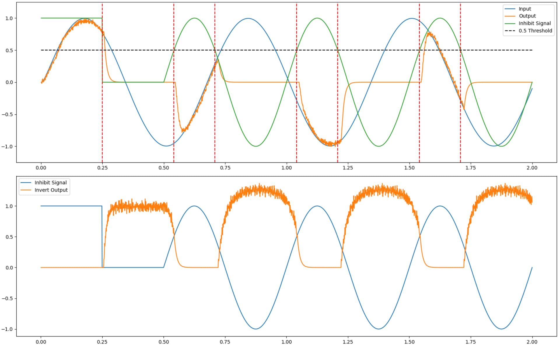
And here is what the output of running the code is:
From the second plot, we see that the output of the inversion ensemble is as we desired. The inversion output (orange) is 0 when the inhibitory signal is 1, and the inversion output is 1 when the inhibitory signal is 0. When the inhibitory signal is below 0, the output of the inversion is greater than 1, but that has no impact on the functionality of the inversion ensemble. Also, note that when the inversion output is 0, there are no spikes produced (the “0” value is not spiky or noisy), which is the desired behaviour for an inhibitory signal.
From the top plot, we can see the inversion ensemble in action. The ensemble output (orange) tracks the input signal (blue), but only when the inhibitory signal (green) is above 0.5 (there is some delay in the inhibition, but that is to be expected). When the inhibitory signal is below 0.5, the output of ens is suppressed, as desired.